


VHDL Style Guide |

|
|
All right strictly reserved. Reproduction or issue to third parties, in any form whatsoever, is not permitted without written authority from the proprietors. |
VHDL Style Guide |
||||
|
Project Name/Projektname |
Page/Seite |
|||||
|
|
|
|||||
|
Prepared / Erstellt |
Subject Responsible / Verantwortlich |
Date/Datum |
Rev. |
File/Datei OpenOffice.org Writer |
||
|
Mario Fohler and Maja Gordić |
Peter Thorwartl |
|
1.0 |
|
||
VHDL STYLE GUIDE

Table of Contents
2. ELEMENTS OF ENTITY/ARCHITECTURE 11
2.1 Generics 11
2.2 Ports 11
2.3 Process 12
2.5 Case 12
2.6 Loops 13
2.7 Functions and Procedures 13
2.8 Components and Component Instantiation 14
2.9 Simulation and Test Benches 14
4. HEADER 18
5. GENERAL CODING RULES FOR DIGITAL DESIGNS 19
7. SVN 27
7.1 Rules 27
8. SCRIPTING 28
“VHDL Style Guide”
A set of rules and guidelines for writing VHDL models used within “So-Logic” company
1. VHDL TERMS
1.1 Objects
An object is a named item that has a value of a given type that belongs to a class.
1.2 Classes
A class is relevant to the nature of the object and represent how the object is used in the model. There are four classes of objects: constants, signals, variables and files.
An object whose value may not be changed
Use constants to define data parameters and table lookups
Constant shall be used to represent limits and parameters
Constant Name: constant_name_c
Example: (modulator_pkg.vhd)
...
package modulator_pkg is
constant per_c : time := 20 ns; -- clock period (T=1/50 MHz), that is used in all testbenches
constant design_setting_c : design_setting_t := (x"ff", 1.0, 3.5, 8, 12);
-- definitions of system clock frequencies for different development boards:
constant spartan3e_dev_board_fclk_c : real := 50000000.0;
constant spartan6_dev_board_fclk_c : real := 200000000.0;
…
An object with a past history
Use signals as channels of communication between concurrent statements (e.g. components, processes)
Keep the same signal name through different hierarchies. Tracing the signals will be easier
Use a prefixes to name the source of the signal, maybe a underscore and the destination of the signal
Use a suffix to describe the function of the signal reset, trigger, en,...
Signal Name: signal_name_s
Example: (modulator_rtl.vhd)
…
architecture rtl of modulator is
signal ampl_cnt_s : std_logic_vector(design_setting_g.depth-1 downto 0); -- amplitude counter
signal sine_ampl_s : std_logic_vector(design_setting_g.width-1 downto 0); -- current amplitude value of the sine signal
signal freq_trig_s : std_logic := '0'; -- signal which frequency depends on the sw0_freq_sel state
…
An object with a single current value
Variables shall be used in preference to signals. Signals carry more overheads than variables do. Unless something needs to be seen in another process, use a variable
In non-synthetisable models, avoid using signals to describe storage element. Use variables instead of signals (signals occupy about two orders more storage than variables during simulation)
In combinatorial processes read variables then write to them. If variables are written then read, long combinatorial logic and latches will be generated. This come from the fact that variables get their value immediately and not like signals after the process suspends
Variable Name: variable_name_v
Example: (pwm_rtl.vhd)
…
begin
process1: process (clk_in)
variable treshold : integer range 0 to 4095 := 0;
variable count : integer range 0 to 4095 := 0;
begin
…
An object used to represent file in the host environment
For portability reasons the only allowed file type is std.textio.text
Don’t use absolute path names
File Handle Name: file_name_f
Example:
...
write_p: process -- write 64 following sin-amplitude values in sin.txt
file out_sin_f: text open write_mode is "sin.txt"; -- create file in write mode in work directory
variable out_sin_line_v : line; -- line variable
begin
wait until rising_edge(clk_in_s);
if wr_end_s = '0' and freq_trig_s = '1' then
if wr_count_s = 64 then -- write 64 amplitude values
wr_end_s <= '1'; -- write end/end of file
else
write(out_sin_line_v, dac_amplvalue_s); -- write dac_amplvalue_s value in out_sin_line_v
writeline(out_sin_f, out_sin_line_v); -- write out_sin_line_v in one line of out_sin_f
wr_count_s <= wr_count_s+1; -- increment write counter
end if;
end if;
end process;
1.3 Types and Subtypes
Use a package for type definitions, if you use it more then once
The type of an object represents its structure, composition and storage requirement (integer, real, std_logic, …) that an object can hold
Type Name: type_name_t_arr --array
_rec --record
_range --range
_enum --enumeration
Example: (modulator_pkg.vhd)
...
package modulator_pkg is
type vector_t_arr is array (natural range <>) of integer;
constant
per_c : time := 20 ns; -- clock period (T=1/50 MHz)
type design_setting_t is record
cntampl_value : std_logic_vector (7 downto 0); -- clk counter amplitude border
f1 : real; -- first frequency for the PWM signal, specified in Hz
f2 : real; -- second frequency for the PWM signal, specified in Hz
depth : integer range 0 to 99; -- the number of samples in one period of the signal
width : integer range 0 to 99; -- the number of bits used to represent amplitude value
end record design_setting_t;
constant design_setting_c : design_setting_t := (x"ff", 1.0, 3.5, 8, 12);
-- definitions of system clock frequencies for different development boards:
constant spartan3e_dev_board_fclk_c : real := 50000000.0;
constant spartan6_dev_board_fclk_c : real := 200000000.0;
function init_sin_f
(
constant depth_c : in integer; -- is the number of samples in one period of the signal (2^8=256)
constant width_c : in integer -- is the number of bits used to represent amplitude value (2^12=4096)
)
return vector_t_arr;
end;
package body modulator_pkg is
function init_sin_f
(
depth_c : in integer;
width_c : in integer
return vector_t_arr is
variable init_arr_v : vector_t_arr(0 to (2 ** depth_c - 1));
begin
for i in 0 to ((2 ** depth_c)- 1) loop -- calculate amplitude values
init_arr_v(i) := integer(round(sin((math_2_pi / real(2 ** depth_c))*real(i)) *
(real(2** (width_c - 1)) - 1.0))) + integer(2 ** (width_c - 1) - 1); -- sin (2*pi*i / N) * (2width_c-1 - 1) + 2width_c-1 – 1, N = 2depth_c
end loop;
return init_arr_v;
end;
end;
1.4 Units
VHDL contains five design units constructs that can be independently analyzed and stored in a design library
Each file shall be named according to the unit it contains
A file shall contain only one design unit. This minimizes the amount of recompilation required when a library unit, on which other library depends, is modified
A library is a collection of compiled design units
Example:
…
library ieee;
use ieee.math_real.all;
use ieee.std_logic_1164.all;
use ieee.std_logic_arith.all;
use ieee.std_logic_textio.all;
use ieee.std_logic_unsigned.all;
library std;
use std.textio.all;
library unisim;
use unisim.vcomponents.all;
…
Represent the interface I/O definition and generics
Make use of generics for buffer sizes, bus width and all other unit parameters. This provides more readability and reusability of the code
File Name: entity_name.vhd
Example: (modulator_rtl.vhd)
…
entity modulator is
generic(
fclk_g: real := spartan3e_dev_board_fclk_c; -- clk frequency specified in Hz
design_setting_g: design_setting_t := design_setting_c --user defined settings for the pwm design
);
port(
clk_in : in std_logic; -- 50 MHz input clock signal
sw0_freq_sel : in std_logic; -- signal made for selecting frequency
pwm : out std_logic -- pulse width modulated signal
);
end;
...
Architecture defines how the system behaves. This description can be in different levels of abstraction or different purpose
Together the entity/architecture pair represents a component
Behavioural beh
Structural structure
Register Transfer Level rtl
Functional fun
Transaction Level Modeling tlm
Testbench tb
Use the company name if it is specific for a company like altera_rtl, xilinx_rtl, lattice_rtl, ...
Use the family name if it is family specific like xc2vp_rtl, xc9500_rtl, ...
File Name: entity_name_architecture_name.vhd
Example: (modulator_rtl.vhd)
...
architecture rtl of modulator is
...
begin
...
end;
...
Provide a collection of declarations (types, constant, signals, component) or sub-programs (procedures, functions).
The subprogram bodies are not described
Where possible, packages approved by the IEEE should be used rather than redeveloping similar functionality
Packages specific to a particular CAD tool standard should not be used
The number of packages used by a model shall not be excessive
File Name: package_name_pkg.vhd
Example: see Chapter 1.3 Types and Subtypes
Provide a complete definition of the subprograms
File Name: package_name_body.vhd
Example: see Chapter 1.3 Types and Subtypes
Binds a particular architecture to an entity or binds an entity/architecture pair to a component
Try to use configuration to map entities and architectures and components in a single file
File Name: config_name_cfg.vhd
2. ELEMENTS OF ENTITY/ARCHITECTURE
2.1 Generics
Generics provide a channel for static information to be communicated to an entity from the environment
Unlike constants, the value can supply externally, either in a component instantiation or in a configuration specification
Avoid using hard-coded numbers for characteristics that may change throughout the lifetime of the model
Name: generic_name_g
Example: (sine_top_rtl.vhd)
…
entity sine_top is
generic(
cntampl_value_g : std_logic_vector := x"ff"; -- threshold value for counter
depth_g : integer range 1 to 99 := 8; -- the number of samples in one period of the signal
width_g : integer range 1 to 99 := 12; -- the number of bits used to represent amplitude value
freqhigh_g : integer := 196608; -- threshold value of frequency a
freqlow_g : integer := 57344 -- threshold value of frequency b
);
…
2.2 Ports
Ports describe the directions of the interface
Use std_logic or std_logic_vector for external port types
Do not use ports with type buffer to read output within the code. Instead use out type and add another variable or signal and assign to it the same output value
Do not use suffixes
Name: port_name
Example: (modulator_rtl.vhd)
...
port(
clk_in : in std_logic; -- 50 MHz input clock signal
sw0_freq_sel : in std_logic; -- signal made for selecting frequency
pwm : out std_logic -- pulse width modulated signal
);
…
2.3 Process
Process enables the designer to write sequential statements like other programming languages
There are two types of processes, clocked and combinatorial
Include all input signals to its sensitivity list. Also include all signals appearing on the right hand side of an assignment or condition present in the process
Processes shall be associated with a descriptive label
Clocked processes should define a reset signal
Name: process_name_p
Example: (counter_rtl.vhd)
…
counter_p: process
begin
wait until rising_edge(clk_in);
if (cnt_en = '1') then
if (cnt_out_s = cnt_value_g - 1) then
cnt_out_s <= (others => '0'); -- counter reset
else
cnt_out_s <= cnt_out_s + 1; -- counter
end if;
end if;
end process;
…
2.4 If/Then/Else
Avoid using more than three levels of if
Avoid using long if-then-else statements and use a case statement. This is to prevent inferring of large priority encoder
Example: see Chapter 2.3 Process
2.5 Case
Choice in a case statement shall be separated by one blank line and intended
Do not use ()
Example: (frequency_trigger_rtl.vhd)
…
freq_ce_p : process -- create and select frequency
begin
wait until rising_edge(clk_in);
freq_cnt_s <= freq_cnt_s + 1; -- increment
freq_trig <= '0';
case sw0_freq_sel is -- select sine frequency
when '0' => -- frequency for sw0_freq_sel = '0'
if (sw0_freq_sel_jmp = '1') then
freq_cnt_s <= 0; -- reset<
sw0_freq_sel_jmp <= '0';
end if;
if (freq_cnt_s = freqlow_g - 1) then
freq_trig <= '1';
freq_cnt_s <= 0; -- reset
end if;
when '1' => -- frequency for sw0_freq_sel = '1'
if (sw0_freq_sel_jmp = '0') then
freq_cnt_s <= 0; -- reset
sw0_freq_sel_jmp <= '1';
end if;
if (freq_cnt_s = freqhigh_g - 1 ) then
freq_trig <= '1';
freq_cnt_s <= 0; -- reset
end if;
when others => null;
end case;
end process;
…
2.6 Loops
Loop statement shall be labeled
Next and exit statement shall specify the loop label the control
Avoid using discrete range, use predefined object attributes
Name: loop_name_l
Example: see Chapter 1.3 Types and Subtypes
2.7 Functions and Procedures
Functions and procedures are used to describe a set of operations or logic that is going to be repeated in many places in the code
A function is a sub-program that returns a value. The function defines how the return value is computed based on the values of the formal parameters
A procedure is a sub-program that performs operations using all the visible parameters and objects, and can modify one or more of the visible parameters
Whenever possible, use constrained arrays, instead of constrained arrays
Named association shall be used preferably to positional association
Name: function_name_f
Name: procedure_name_p
Example: see Chapter 1.3 Types and Subtypes
2.8 Components and Component Instantiation
A component represents an entity/architecture pair
Instantiations of components in architectures is a method to define hierarchy because architectures of components can have within them other components
Components should be labelled
Named association shall be used preferably to positional association
Name: component_name
Use the no additional component declaration for a bottom up approach
Example: (modulator_rtl.vhd)
…
freq_ce : entity work.frequency_trigger(rtl) -- generates frequency trigger
generic map(
freqhigh_g => freqhigh_c,
freqlow_g => freqlow_c
)
port map(
clk_in => clk_in,
freq_trig => freq_trig_s,
sw0_freq_sel => sw0_freq_sel
);
…
2.9 Simulation and Test Benches
Do not assign value of unknowns ‘X’ or check for don’t care ‘-‘. Such values can produce unexpected behaviour in both simulation and syntheses
Do not use default values or initialization for signals and variables. Such assignment can cause mismatch between synthesis and simulation
The verification shall solely be performed using the VHDL test benches; no simulator specific featured or commands shall be used
Test benches should be self-checking, reporting success or failure for each subtest
Name: entity_name_tb.vhd
Example: (modulator_tb.vhd)
library ieee;
use ieee.std_logic_1164.all;
use ieee.std_logic_arith.all;
use ieee.std_logic_textio.all;
use ieee.std_logic_unsigned.all;
use work.modulator_pkg.all;
entity modulator_tb is
generic(
design_setting_g: design_setting_t := design_setting_c --user defined settings for the pwm design
);
end;
architecture tb of modulator_tb is
signal clk_in_s : std_logic := '1'; -- 50 MHz input clock signal
signal sw0_freq_sel_s : std_logic := '1'; -- signal made for selecting frequency
signal pwm_s : std_logic := '0'; -- pulse width modulated signal
begin
pwmmodulator : entity work.modulator -- fetch generics and ports of modulator_rtl.vhd
generic map(
fclk_g => 1000000000.0/real (per_c/(1 ns)),
design_setting_g => design_setting_g
)
port map(
clk_in => clk_in_s,
sw0_freq_sel => sw0_freq_sel_s,
pwm => pwm_s
);
clk_in_s <= not (clk_in_s) after per_c/2; -- generates 50 MHz input clock signal
sw0_freq_sel_s <= '1', '0' after 25 us;
end;
2.10 Types
Use std_logic_arith, std_logic_unsigned/std_logic_signed packages. This provides the essential conversion functions:
.conv_integer (<signal_name>):
converts std_logic_vector, unsigned, and signed data types into an integer data type
.conv_unsigned (<signal_name>, <size>):
converts a std_logic_vector, integer, unsigned (change size), or signed data types into an unsigned data type
.conv_signed (<signal_name>, <size>):
converts a std_logic_vector, integer, signed (change size), or unsigned data types into a signed data type
.conv_std_logic_vector (<signal_name>, <size>):
converts an integer, signed, or unsigned data type into a std_logic_vector data type
.ext (<signal_name>, <size>):
zero extends a std_logic_vector to size <size>
.sxt (<signal_name>, <size>):
sign extends a std_logic_vector to size <size>
All conversion functions can take for the <signal_name> data-type a std_logic_vector, unsigned, signed, std_ulogic_vector, or integer. <size> is specified as an integer value.
3. VHDL STYLE GUIDE
Denotation:
Do not use different VHDL coding standards in the same project
Use VHDL-93
Everything (all VHDL keywords and all user-defined identifiers) shall be in lower case
All user-defined identifiers shall be meaningful composed from words separated by underscores, based on the English language
Use the same identifier name for the actual hardware and in the data sheet
For signals and variables that are active low, this should be clearly indicated by their suffixing “_n” as in “reset_n”
Named association should be used preferably to positional association
For objects that are global, this should be clearly indicated by their suffix “_gc”
Underscores should be used in literals
Only literals in base 2, 8, 10, 16 should be used
Extended digits in base-16 literals should be written in the lower case
Variable width ports should be constrained using generics
Positioning:
Declarative regions and blocks should be indented by four spaces
Indentation level in sequential statements should not exceed 4
Indented regions in sequential statements should not have more than 60 lines
The TAB character should not be used to indent, only use the space character
Lines should not exceed 120 characters
Long lines should be broken where there are white spaces
Line continuations should be indented to line-up with the first token at the same nesting level or by four spaces
One line should separate concurrent statements and their descriptive comment
Groups of logically related statements and declarations should be separated by one blank line
Unless otherwise specified, tokens should be separated by one space
No space should precede a close parenthesis or semi-colon
No space should surround a single quote or dot
Each statement should start on a new line
Each declaration should start on a new line
Elements in interface declarations should be vertically aligned
Elements in signal, constant declarations should be vertically aligned
Elements in a named association that spans more than one line should be vertically aligned
Buffer and linkage ports should not be used
Guarded blocks and guarded signals should not be used
Operators should not be overloaded lightly
Attributes ‘range and ‘reverse_range should be used when scanning arrays
Enumerates should be used to represent non-arithmetic discrete values
Use too many parentheses, never let the tool resolve precedence. Explicitly declare precedence via parenthesis
Use relative paths
Include only libraries which are really used in the design!
For interfacing other modules use only std_logic and std_logic_vector types
For arithmetic operations use library ieee.std_logic_signed_bit.all and ieee.std_logic_signed.all
Use preferred libraries ieee.std_logic_1164.all, std.text.all and std.logic_textio.all
Comments:
Comments should be immediately followed by the code they describe
Comments for port and signal declarations should be in the same line
Each file should have descriptive comment of its content, located at the top of the file
4. HEADER
--------------------------------------------------------------------------------
-- File : modulator_rtl.vhd
-- Project : modulator
-- Creation : 15.07.2008
-- Limitations : none
-- Errors : none known
-- Simulator : ISim
-- Synthesizer : ISE 10.1
-- Platform : Windows XP
-- Targets : Simulation, Synthese, Implementation
---------------------------------------
-- Naming conv. : so_vhdl_guide_.doc
---------------------------------------
-- Authors : Peter Thorwartl (thor)
-- Organization : so-logic
-- Email : thor@so-logic.co.at
-- Address : Lustkandlg. 52/22, A-1090 Vienna Austria/Europe/Earth
--------------------------------------------------------------------------------
-- Copyright Notice
-- Copying of this document and giving it to others and the
-- communication of the contents thereof is forbidden without authority.
-- Offenders are liable to payment of damages. All rights are reserved in
-- event of the grant or patent of the utility model or design.
--------------------------------------------------------------------------------
-- Function description
-- This module will merge all the previously designed modules
--------------------------------------------------------------------------------
-- $HeadURL:$
-- $Date:$
-- $Author:$
-- $Revision:$
--------------------------------------------------------------------------------
5. GENERAL CODING RULES FOR DIGITAL DESIGNS
5.1 Reset
Do not assign an asynchronous reset to sequential statements
For simulation use default value assignment in signal declaration
5.2 Clocks
Use only synchronous design techniques
Example: (modulator_rtl.vhd)
…
entity modulator is
generic(
...
);
port(
clk_in: in std_logic; -- 50 MHz input clock signal
...
);
end;
architecture rtl of modulator is
...
begin
freq_ce : entity work.frequency_trigger(rtl) -- generates frequency trigger
generic map(
...
)
port map(
clk_in => clk_in,
...
);
counterampl : entity work.counter(rtl) -- generates amplitude values
generic map(
...
)
port map (
clk_in => clk_in,
...
);
sine : entity work.sine(rtl) -- generates digital sine
generic map(
...
)
port map(
clk_in => clk_in,
...
);
pwmmodule : entity work.pwm (rtl) -- generates pwm signal
generic map(
...
)
port map (
clk_in => clk_in,
...
);
end;
Do not use gated clocks
Do not generate internal clock signal in modules
Avoid using latches
Do not use buffers as delay elements
All block's external IOs should be registered
Avoid using both clock edges
Clock signal must be connected to global dedicated routing resources
Do not use clock or reset as data or as enable
Do not use data as clock or as reset
Signals that cross-different clock domains should be sampled before and after crossing domains (double sampling is preferred to minimize meta-stability)
Use the lowest possible clock speed in each clock domain
Use the minimum number of clock domains
Use clock enables
Clock enables can only be inferred in a clocked process
Clock enables can be inferred explicitly by testing an enable signal. If the enable is true, the signal is updated. If enable is false, that signal will hold its current value
Clock enables can be implicitly inferred in two ways:
Not assigning to a signal in every branch of an if-then-else statement or case statement. Remember that latches will be inferred for this condition in a combinatorial process
Not defining all possible states or branches of an if-then-else or case statement
Use Digital Clock Manager like DCMs, DLLs, …
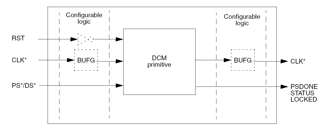
Illustration
5.1: DCM module block diagram
5.3 Buses
Start buses with the LSB
Use MSB to LSB for data buses
Use LSB to MSB for delay lines and shift registers
Start counting from one
Avoid using internal tri-state signals, they no longer exist on FPGAs. They will be modelled with two buses, one for reading and one for writing
5.4 Finite State Machine (FSM)
Generally, use three process statements for a state machine: one process for next-state decoding, one for output decoding, and one for the registering of state bits and outputs
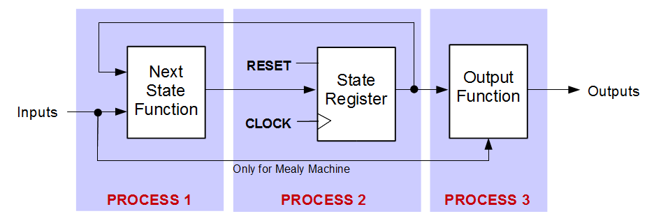
Illustration
5.2: FSM with three processes diagram
Use a Mealy look-ahead state machine with registered outputs whenever possible, or use a Moore state machine with next-state output decoding and registered outputs to incur the minimum amount of latency
Use enumeration types for the states
Use one hot encoding for FPGAs
Use binary, Gray, sequential coding for CPLDs
Example:
library ieee;
use ieee.std_logic_1164.all;
entity fsm_3_processes is
port (
clk : in std_logic
reset : in std_logic
x1 : in std_logic;
outp : out std_logic
);
end;
architecture beh of fsm_3_processes is
type state_type is (s1,s2,s3,s4);
signal state, next_state: state_type ;
begin
process1: process (clk,reset)
begin
if (reset = '1') then
state <= s1;
elsif (clk = '1' and clk'Event) then
state <= next_state;
end if;
end process;
process2 : process (state, x1)
begin
case state is
when s1 =>
if x1 = '1' then
next_state <= s2;
else
next_state <= s3;
end if;
when s2 => next_state <= s4;
when s3 => next_state <= s4;
when s4 => next_state <= s1;
end case;
end process;
process3 : process (state)
begin
case state is
when s1 => outp <= '1';
when s2 => outp <= '1';
when s3 => outp <= '0';
when s4 => outp <= '0';
end case;
end process;
end;
5.5 Memories
Use synchronous single-port or dual-port block memories for synchronous read and write
Use asynchronous distributed RAMs for synchronous write and asynchronous read
Example:
library ieee;
use ieee.std_logic_1164.all;
use ieee.std_logic_unsigned.all;
entity rom is
port (
clk : in std_logic;
en : in std_logic;
addr : in std_logic_vector(5 downto 0);
data : out std_logic_vector(19 downto 0)
);
end;
architecture syn of rom is
type rom_type is array (63 downto 0) of std_logic_vector (19 downto 0);
constant ROM :
rom_type:= (X"0200A", X"00300", X"08101",
X"04000", X"08601",
X"0233A",
X"00300", X"08602", X"02310",
X"0203B",
X"08300",
X"04002", X"08201", X"00500",
X"04001",
X"02500",
X"00340", X"00241", X"04002",
X"08300",
X"08201",
X"00500", X"08101", X"00602",
X"04003",
X"0241E",
X"00301", X"00102", X"02122",
X"02021",
X"00301",
X"00102", X"02222", X"04001",
X"00342",
X"0232B",
X"00900", X"00302", X"00102",
X"04002",
X"00900",
X"08201", X"02023", X"00303",
X"02433",
X"00301",
X"04004", X"00301", X"00102",
X"02137",
X"02036",
X"00301", X"00102", X"02237",
X"04004",
X"00304",
X"04040", X"02500", X"02500",
X"02500",
X"0030D",
X"02341", X"08201", X"0400D");
begin
process
(clk)
begin
if
(clk'event and clk = '1') then
if (en
= '1') then
data <=
ROM(conv_integer(addr));
end if;
end if;
end process;
end;
6. PROJECT STRUCTURE
6.1 Library
Directory Structure Example:
/lib
/vhdl
/isim11.4
/verilog
/isim11.4
/pads
/templates
/oo
/lib - is the location for project libraries, templates, shared files for multiple projects
/vhdl - for vhdl libraries
/verilog - for verilog libraries
/pads - for layout software symbols, parts, decals
/templates - for OpenOffice examples
6.2 Project Directory
Project Directory Example:
project/
/<company_name1>
/<project_name1>
/<project_name2>
/<company_name2>
/<project_name3>
/<project_name4>
<project> - is the root of all projects developed by the company and can be readable for all staff members
<company> - company name of the customer
<project_name> - is the formal name of the project under development, used also for svn and time table entries
6.3 One Project Tree
<project-name>/
info/
/xilinx
/marvell
- pcb/
soft/
tools/
upld/
/info - additional information from the customer or websites
/pcb - schematic and layout files, also production data like gerber and excellon files and searchable PDF of schematic and layout
/upld - is the location for the FPGA, CPLD, … data
/soft - directory for additional software, like drivers
/tools - additional tools
/pcb - is the location for the layout data
6.4 UPLD User Programmable Logic Devices
/upld
/src
/result
/release
/src - everything inside the source directory should be under version control, no binary files
No version numbers in file names under revision control
/result - temporary files generated from the tools in subdirectories with the <toolname>\, like ise91sp3, ise82sp3, edk91sp2, msim61f, pads2007, matlab2006b
/release - subdirectory with some kind of design names
automatically generated zip files include src dir report files and programming file ( *.mcs, *.bit, *.elf, *.svf,...) with the name of the tag
src\.
doc\.
figure\.
*.png
*.vsd
html\.
pdf\.
c\.
*.c
*.cpp
*.h
java\.
*.java
vhdl\.
*.vhd
verilog\.
*.v
<toolcompany>\*<toolversion_confname>.*cmd\
*.make
*.bat
*.sh
6.5 File Name
Give short but meaningful names
Use only lower case characters
Do not use special characters. Only alphanumeric and underscore to separate two sub-strings, are allowed. Do not use spaces
Name big things first, like cpu_register, not register_cpu !
Use only English terms, avoid keywords or commands
Good names are part of the documentation
Rename names if you change the functionality
The structure of the file system hierarchy should mirror the logical structure of the system being modelled. A directory should correspond to one and only one design unit
Do not use version numbers, if the files are under version control like SVN
7. SVN
7.1 Rules
All sources will be kept on the So-Logic server and revision controlled by SVN. For off line work you will be able to copy the sources to a local directory. \<project_name>\.svn
The header fields will be automatically updated every time you check in your source codes
Tag the files every time you make a release (sending a bitstream to the customer or reaching a milestone)
Command line: https://svn01.so-logic.net/projects
Web interface svn web-interface: https://svn01.so-logic.net/websvn
Use the default layout structure of SVN
o /trunk ... the head version
o /branches ..different version, normally merged back to trunk
o /tags ..named version or milestones
Commit your changes every time and add comments!
Tag if you need to go back to exact version
8. SCRIPTING
Use two make files
One called Makefile, that has many targets. To call the real makefile, type something like so_demo.make
Use only relative paths
Add help for different targets
Remove unnecessary targets
Use automatic name to number conversion for ID generation. Use names for bitstream and when you are reading back from CPUs
Try to automate all steps in the design flow
Try to be compatible with graphical tools
8.1 Identifier ID
Examples for using 32-bit identification number:
# VERSION string digit 12345678
# 1. digit year
# 2. and 3. digit week
# 4. day of week 1 Monday 7 .. Sunday
# 5. digit PROJECT
# 0 .. so_hs
- ifeq ($(PROJECT), so_hs)
P=0
endif
ifeq ($(PROJECT), infineon_hs)
P=1
endif
# 6. digit DESIGN
# 0 .. iotest check pinout, GTP and DCM use for all use cases
- ifeq ($(DESIGN), iotest)
S= 0
endif
# 1 .. pcbtest with CPU
- ifeq ($(DESIGN), pcbtest)
S = 1
endif
# 2 .. ibert serial io toolkit
- ifeq ($(DESIGN), ibert)
S= 2
endif
# 3 .. HSPG
- ifeq ($(DESIGN), hspg)
S = 3
endif
# 4 .. HSLA
- ifeq ($(DESIGN), hsla)
S = 4
endif
# 6 .. HSPL_L
- ifeq ($(DESIGN), hspl_l)
S = 6
endif
# 7 .. HSPL_TV
- ifeq ($(DESIGN), hspl_tv)
S = 7
endif
# 8 .. HSPL_TJ
- ifeq ($(DESIGN), hspl_tj)
S = 8
endif
# 7. digit BOARD
# 0 .. ML505 Demoboard Xilinx
- ifeq ($(BOARD), ml505)
B=0
endif
# 1 .. first version of print FPGA board
- ifeq ($(BOARD), hsfb1)
B=1
endif
# 8. digit PART
- ifeq ($(PART), lx50t)
DEVICE=xc5vlx50t-ff1136-1
T=0
endif
ifeq ($(PART), lx110t)
DEVICE=xc5lvx110t-ff1136-1
T=1
endif
ifeq ($(PART), fx70t)
DEVICE=xc5vfx70t-ff1136-1
T=2
endif
ifeq ($(PART), fx100t)
DEVICE=xc5vfx100t-ff1136-1
T=3
endif