3. COUNTER
3.1 Description
- Usage: This module will be an universal (generic) counter. It's task will be to generate read addresses for the ROM where samples of the sine wave are stored. The speed of the counting will be controlled by the Frequency Trigger module, via freg_trig port, and the output of the Counter module will be an input of the Digital Sine module.
- Block diagram:
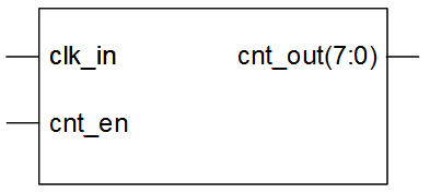
Drawing 3.1: Counter block diagram
- Input ports:
- clk_in: input clock signal
- cnt_en: counter enable
- Output ports:
- cnt_out: current counter value
- Generics:
- cnt_value_g: threshold value for counter
- depth_g: the number of samples in one period of the signal
- File name: counter_rtl.vhd
3.2 Creating Module
As we already said, for better designs, our recommendation is not to use the GUI module inserter. Instead of that, create a module in an text editor, rename it to module_name.vhd and insert it into your project.
Counter VHDL model:
library ieee;
use ieee.std_logic_1164.all;
use ieee.std_logic_arith.all;
use ieee.std_logic_unsigned.all;
entity counter is
generic(
cnt_value_g : integer; -- threshold value for counter
depth_g : integer – the number of samples in one period of the signal
);
port(
clk_in : in std_logic; -- input clock signal
cnt_en : in std_logic; -- counter enable
cnt_out : out std_logic_vector (depth_g - 1 downto 0) -- current counter value
);
end;
architecture rtl of counter is
signal cnt_out_s : std_logic_vector (depth_g - 1 downto 0) := (others => '0'); -- current counter value
begin
counter_p: process
begin
wait until rising_edge(clk_in);
if (cnt_en = '1') then
if (cnt_out_s = conv_std_logic_vector (cnt_value_g, depth_g)) then
cnt_out_s <= (others => '0'); -- counter reset
else
cnt_out_s <= cnt_out_s + 1; -- counter
end if;
end if;
end process;
cnt_out <= cnt_out_s;
end;
- In the Hierarchy window, left-click on the module_name (counter – rtl) and then in the Processes window double-click on the Check Syntax option
- Note: Please bear in mind that the Implementation option in the Hierarchy window must be selected.
- Correct any errors before proceeding
3.3 Creating Test Bench
- Usage: used to verify correct operation of the counter module defined in the counter_rtl.vhd file
- Test bench internal signals:
- clk_in_s: input clock signal
- cnt_en_s: counter enable
- cnt_out_s: current counter value
- Generics:
- cnt_value_g: threshold value for counter
- depth_g: the number of samples in one period of the signal
- File name: counter_tb.vhd
We will now create a test bench file for the Counter module (counter_tb.vhd). We will use the same steps as for creating frequency_trigger_rtl.vhd module, explained in Sub-chapter 2.3.1 Creating a Module Using an Text Editor.
Counter test bench:
library ieee;
use ieee.std_logic_1164.all;
use ieee.std_logic_arith.all;
use ieee.std_logic_unsigned.all;
use work.modulator_pkg.all;
-
entity counter_tb is
generic(
cnt_value_g : integer := 4; – threshold value for counter
depth_g : integer := 3 – the number of samples in one period of the signal
);
end;
architecture tb of counter_tb is
signal clk_in_s : std_logic := '1'; -- input clock signal
signal cnt_en_s : std_logic := '0'; -- counter enable
signal cnt_out_s : std_logic_vector (depth_g - 1 downto 0) := (others => '0'); -- current counter value
begin
counter : entity work.counter(rtl) -- counter instance
generic map(
cnt_value_g => cnt_value_g,
depth_g => depth_g
)
port map (
clk_in => clk_in_s,
cnt_en => cnt_en_s,
cnt_out => cnt_out_s
);
clk_in_s <= not (clk_in_s) after per_c/2; -- generates 50 MHz input clock signal
cnt_en_s <= '1' after 100 ns, '0' after 120 ns, '1' after 160 ns, '0' after 180 ns, '1' after 220 ns, '0' after 240 ns, '1' after 320 ns, '0' after 340 ns, '1' after 420 ns, '0' after 440 ns;
end;
After adding counter_tb.vhd file into modulator project, it should appear in the Hierarchy window, under the modulator project. Please bear in mind that the Simulation option in the Design View must be selected, see Illustration 3.1.
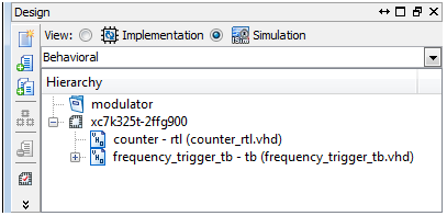
Illustration 3.1: counter_tb.vhd file in the Hierarchy window
3.4 Simulating
After you have entered the code for the input stimulus in order to perform simulation, follow the next steps:
- In the Design window, select Implementation view
- In the Hierarchy window, select counter – rtl module, right-click on it and choose Set as Top Module option, see Illustration 3.2
- In the Set as Top Module dialog box, click Yes, see Illustration 3.3
- Turn back to the Design window and select Simulation view
- If necessary, select Behavioral Simulation from the drop-down list
- Select testbench_name (counter_tb.vhd) in the Hierarchy window
- In the Processes window, expand ISim Simulator and double-click on the Behavioral Check Syntax
- Correct any errors before proceeding
- In the Processes window, expand ISim Simulator and then double-click on the Simulate Behavioral Model, see Illustration 3.4
- Assuming no errors in the ISim command line, your simulation result should look similar to Illustration 3.5
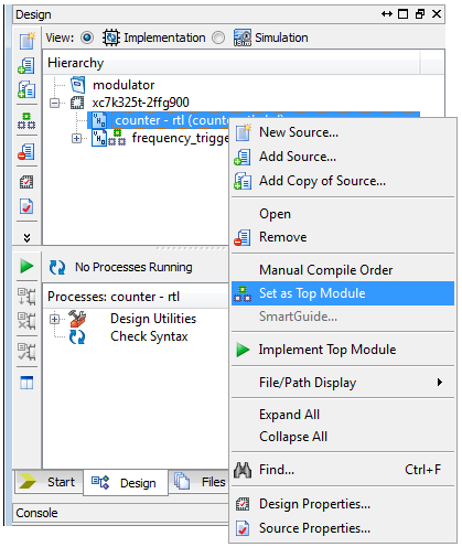
Illustration 3.2: Set as Top Module option
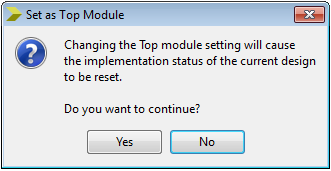
Illustration 3.3: Set as Top Module dialog box
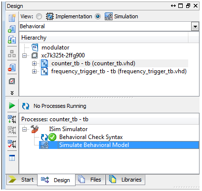
Illustration 3.4: Simulate Behavioral Model command
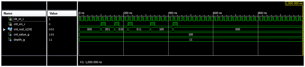
Illustration 3.5: Simulation Results
Note: All the information about creating the Counter Module, generating its test bench and simulating the Counter design, you can also find in the Lab 5: “Creating Counter Module”.