4. SINE PACKAGE
4.1 Description
-
Usage: In our case we will make an VHDL package with a parametrized sine signal. Total of 28=256 unsigned amplitude values during one sine-period will be stored into an ROM array.
In order to simplify the generation of the PWM signal, we will use the sine wave signal that is shifted upwards. The value of this shift will be selected in a way to make all values of the sine signal positive. This is illustrated on the Drawing 4.1.
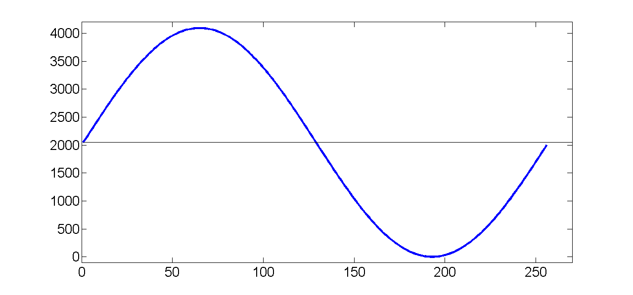
Drawing 4.1: Sine-package description
The formula for calculating the sine wave shown on the Drawing 4.1 is:
|
sin (2*pi*i / N) * (2width_c-1 - 1) + 2width_c-1 - 1, N = 2depth_c |
depth_c - is the number of samples in one period of the signal (28=256)
width_c - is the number of bits used to represent amplitude value (212=4096)
This formula is defining the nature of the desired sine signal:
- sin (2*pi*i / N) - is telling us that the signal is periodic, with 2*pi period; i is the current sample value (from 0 to 255) and N is the number of samples in one period of the signal
- *(2width_c-1 -1) – is telling us that the amplitude of the sine signal is 2047
-
+ 2width_c-1 -1 – is telling us that the DC value of the sine signal is 2047, which means that the whole sine signal is shifted up
- File name: modulator_pkg.vhd
4.2 Creating Module
To create a Sine package module, use steps for creating modules, Sub-chapter 2.3.1 Creating a Module Using an Text Editor.
Sine package VHDL model:
library ieee;
use ieee.math_real.all;
use ieee.std_logic_1164.all;
use ieee.std_logic_arith.all;
use ieee.std_logic_unsigned.all;
package modulator_pkg is
type module_is_top_t is (yes, no); -- only the top module can instantiate a diff clk buffer
type board_type_t is (lx9, zedboard, ml605, kc705);
type has_diff_clk_t is (yes, no);
type board_setting_t is record
board_name : board_type_t;
fclk : real;
has_diff_clk : has_diff_clk_t;
end record board_setting_t;
-- place the information about the new boards here:
constant lx9_c : board_setting_t := (lx9, 100000000.0, no); -- Spartan-6
constant zedboard_c : board_setting_t := (zedboard, 100000000.0, no); -- Zynq-7000
constant ml605_c : board_setting_t := (ml605, 200000000.0, yes); -- Virtex-6
constant kc705_c : board_setting_t := (kc705, 200000000.0, yes); -- Kintex-7
type Software_environment is (ISE, Vivado, EDK);
type vector_t_arr is array (natural range <>) of integer;
constant per_c : time := 20 ns; -- clock period (T=1/50 MHz), that is used in almost all testbenches
type design_setting_t is record
cntampl_value : integer; -- counter amplitude border, it's value should be equal to (2^depth)-1
f_low : real; -- first frequency for the PWM signal, specified in Hz
f_high: real; -- second frequency for the PWM signal, specified in Hz
depth : integer range 0 to 99; -- the number of samples in one period of the signal
width : integer range 0 to 99; -- the number of bits used to represent amplitude value
end record design_setting_t;
constant design_setting_c : design_setting_t := (255, 1.0, 3.5, 8, 12);
function init_sin_f
(
constant depth_c : in integer; -- is the number of samples in one period of the signal (28=256)
constant width_c : in integer -- is the number of bits used to represent amplitude value (212=4096)
)
return vector_t_arr;
end;
package body modulator_pkg is
function init_sin_f
(
constant depth_c : in integer;
constant width_c : in integer
)
return vector_t_arr is
variable init_arr_v : vector_t_arr(0 to (2 ** depth_c - 1));
begin
for i in 0 to ((2 ** depth_c)- 1) loop -- calculate amplitude values
init_arr_v(i) := integer(round(sin((math_2_pi / real(2 ** depth_c))*real(i)) * (real(2 ** (width_c - 1)) - 1.0)))
+ integer(2 ** (width_c - 1) – 1);
-- sin (2*pi*i / N) * (2width_c-1 - 1) + 2width_c-1 – 1, N = 2depth_c
end loop;
return init_arr_v;
end;
end;
Note: All the information about creating the sine package, you can also find in the Lab 6: “Creating Sine Package”.