5. DIGITAL SINE
5.1 Description
-
Usage: This module will generate an digital representation of an analog (sine) signal with desired frequency. It will use the counter values as addresses to fetch the next value of the sine wave from the ROM.
Note: Don't forget to include the Sine package in the code of the Digital Sine module!
- Block diagram:
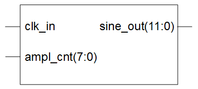
Drawing 5.1: Digital Sine block diagram
- Input ports:
- clk_in: input clock signal
- ampl_cnt: address value for the sine waveform ROM
- Output ports:
- sine_out: current amplitude value of the sine signal
- Generics:
- depth_g: the number of samples in one period of the signal
- width_g: the number of bits used to represent amplitude value
- File name: sine_rtl.vhd
5.2 Creating Module
To create Digital Sine module, use steps for creating modules, Sub-chapter 2.3.1 Creating a Module Using an Text Editor.
Digital Sine VHDL model:
library ieee;
use ieee.std_logic_1164.all;
use ieee.std_logic_arith.all;
use ieee.std_logic_unsigned.all;
use work.modulator_pkg.all;
entity sine is
generic(
depth_g : integer range 1 to 99 := 8;
width_g : integer range 1 to 99 := 12
);
port(
ampl_cnt : in std_logic_vector(depth_g-1 downto 0); -- address value for the sine waveform ROM
clk_in : in std_logic; -- input clock signal
sine_out : out std_logic_vector(width_g-1 downto 0) -- current amplitude value of the sine signal
);
end;
architecture rtl of sine is
constant sin_ampl_c : vector_t_arr := init_sin_f(depth_g, width_g); -- returns sine amplitude value
signal ampl_cnt_s : integer range 0 to 255 := 0; -- amplitude counter
signal sine_s : std_logic_vector(width_g-1 downto 0) := (others=>'0'); -- sine
begin
sine_p : process -- fetch amplitude values and frequency - generates sine
begin
wait until rising_edge(clk_in);
ampl_cnt_s <= conv_integer(ampl_cnt); -- convert amplitude counter into integer
sine_s <= conv_std_logic_vector(sin_ampl_c(ampl_cnt_s), width_g); -- fetch amplitude
end process;
sine_out <= sine_s;
end;
Note: All the information about creating the Digital Sine Module, you can also find in the Lab 7: “Creating Digital Sine Module”.