2. FREQUENCY TRIGGER
2.1 Description
- Usage: This module will generate one output signal with two possible frequencies, one with 256 Hz and the second one with 896 Hz. Which frequency will be chosen depends on the position of the two-state on-board switch (sw0).
- Block diagram:
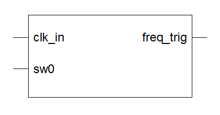
Drawing 2.1: Frequency Trigger block diagram
- Input ports:
- clk_in: input clock signal
- sw0: input signal from the on-board switch, used for changing output signal frequency
- Output ports:
- freq_trig: output signal which frequency depends on the state of the sw0 input signal (256 Hz or 896 Hz)
- Generics:
- div_factor_freqhigh_g: input clock division factor when sw0 = '1'
- div_factor_freqlow_g: input clock division factor when sw0 = '0'
- File name: frequency_trigger_rtl.vhd
2.2 Creating a New Project
The first step in creating a new design will be to create a new project. We will create a new project using the ISE New Project wizard. The New Project wizard will create an XISE project file for us. It will be place where ISE will organize our design files and save the design status whenever the processes are run.
To create a new project:
-
Launch ISE Design Suite 14.7:
Select Start → All Programs → Xilinx Design Tools → ISE Design Suite 14.7 → ISE Design Tools → Project Navigator and the ISE Project Navigator main window will appear
- In the Project Navigator, select File / New Project... from the main menu or click on the New Project... command in the Start window
-
In the Create New Project dialog box:
- enter project_name (in our case it will be modulator) in the Name field, see Illustration 2.1
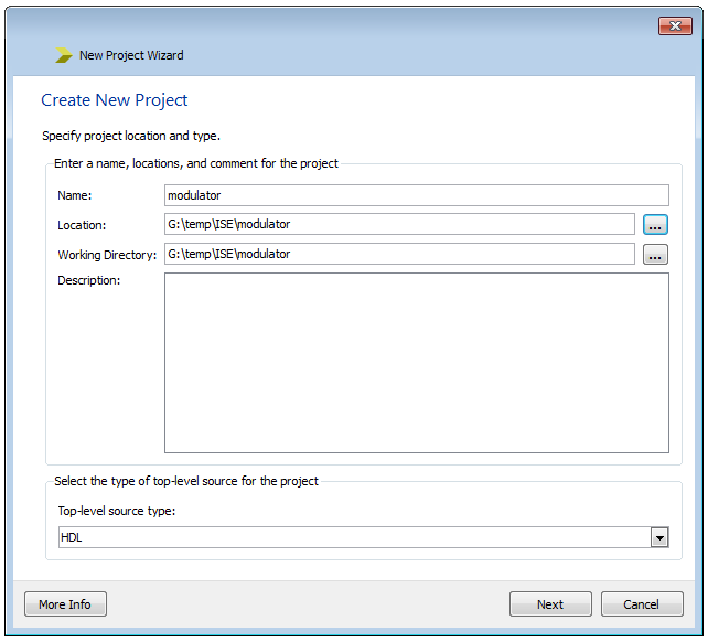
Illustration 2.1: Create New Project dialog box
-
- Browse the location and working directory of your project in the Location and Working Directory fields
Note: This option will automatically generate a project folder, with the same name as a project name, and place it in the selected working directory.
-
- Verify that the HDL option has been selected from the Top-level source type drop-down list
- Click Next
- In the Project Settings dialog box set the following parameters as it is shown on the Illustration 2.2:
- Product Category: All
- Family: Kintex7
- Device: XC7K325T
- Package: FFG900
- Speed: -2
- Synthesis Tool: XST (VHDL/Verilog)
- Simulator: ISim (VHDL/Verilog)
- Preferred Language: VHDL
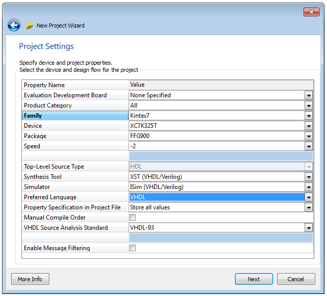
Illustration 2.2: Project Settings dialog box
- Leave all other parameters unchanged and click Next
- In the Project Summary dialog box click Finish if you are satisfied with the summary of your project, see Illustration 2.3. If you are not satisfied, you must go ones more through the whole procedure to correct all the questionable issues.
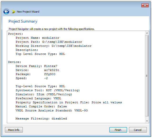
Illustration 2.3: Project Summary dialog box
After we finished with the new project creation process, in a few seconds ISE Project Navigator will create empty modulator project for us, see Illustration 2.4
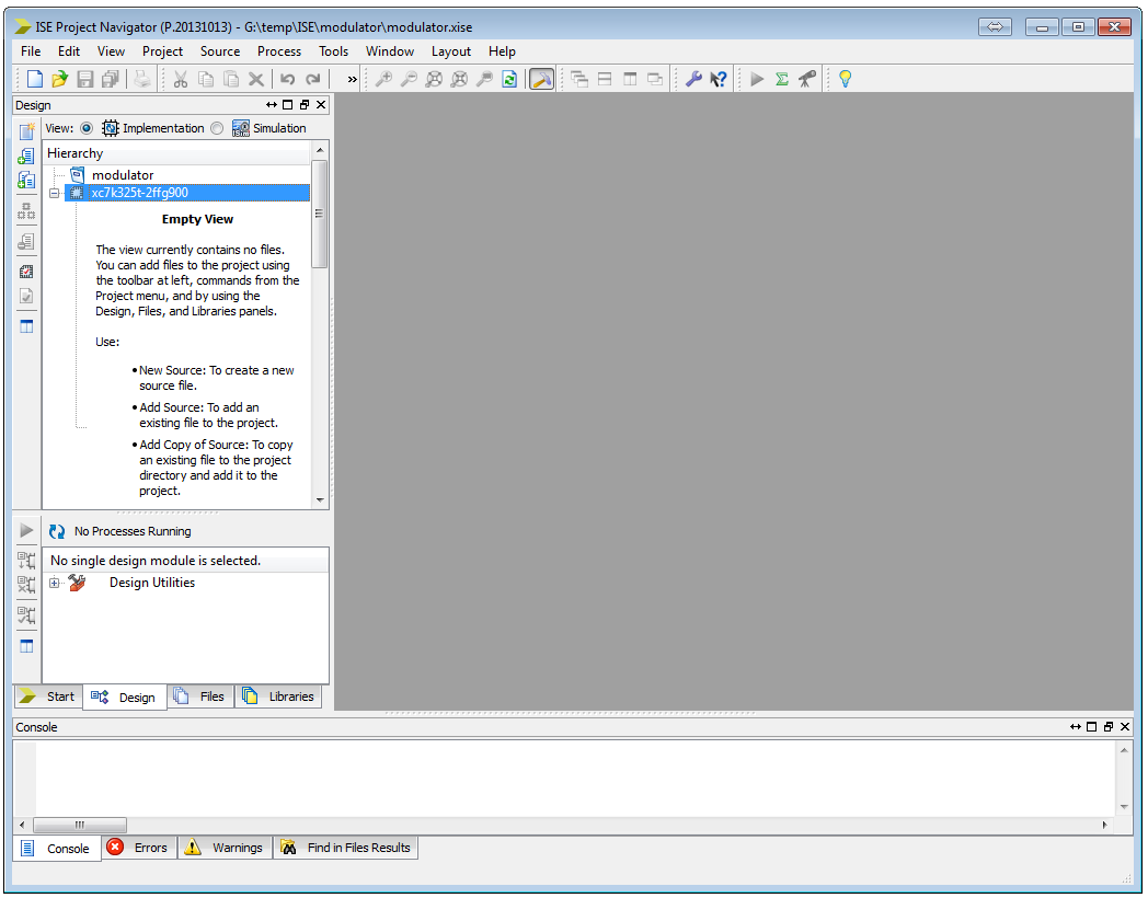
Illustration 2.4: Project Navigator with created modulator project
2.3 Creating Module
To create a new module, follow the steps:
- In the ISE Project Navigator, select Project / New Source... option from the main menu or click on the New Source button in the Design window, see Illustration 2.5
- In the Select Source Type dialog box, see Illustration 2.6, select VHDL Module, enter module_name (in our case it will be frequency_trigger_rtl) in the File name field and click Next to open the Define Module dialog box
- In the Define Module dialog box enter entity_name (frequency_trigger) in the Entity name field and architecture_name (rtl) in the Architecture name field
- Specify ports for the intended module as it is shown on the Illustration 2.7
- Click Next
- In the Summary dialog box, see Illustration 2.8, click Finish if you are satisfied with the summary of the Frequency Trigger module and your source file (frequency_trigger_rtl.vhd) should appear in the Hierarchy window, under the modulator project, see Illustration 2.9
- Double-click on the created frequency_trigger_rtl.vhd source file to see what the toll has created for us, see Illustration 2.10
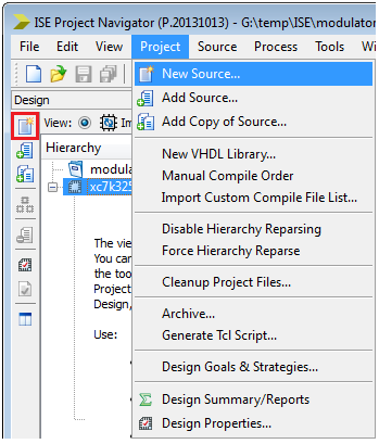
Illustration 2.5: New Source option
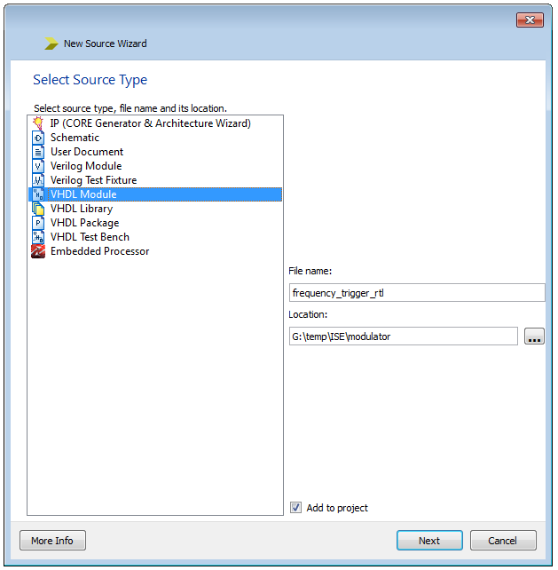
Illustration 2.6: Select Source Type dialog box – VHDL Module
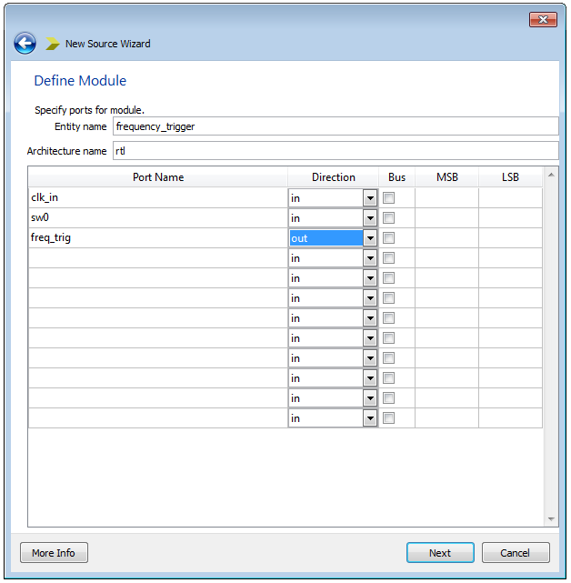
Illustration 2.7: Define Module dialog box with specified ports for Frequency Trigger module
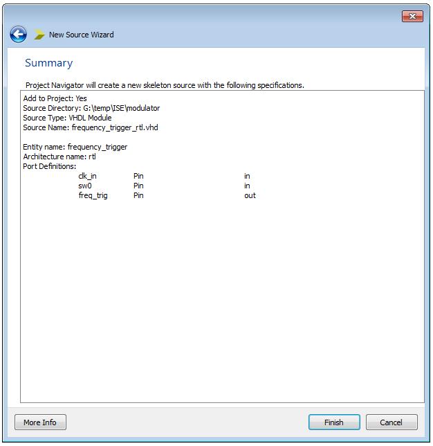
Illustration 2.8: Summary dialog box of Frequency Trigger module
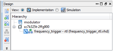
Illustration 2.9: frequency_trigger_rtl.vhd source file in the Hierarchy window
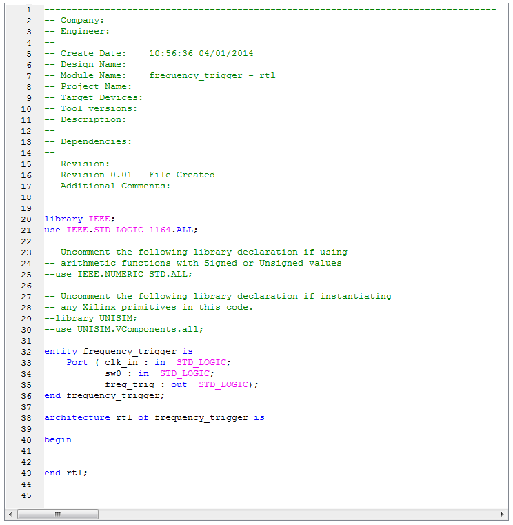
Illustration 2.10: Automatically generated frequency_trigger_rtl.vhd source code
As you can see from the illustration above, the tool automatically creates a default header and the entity declaration based on the data that you entered.
Important: The automatically generated code is not very handsome and clear, and the recommendation is to modify it. Here are the steps for modifying:
- create a module header as comment
- set all text to lower case
- remove all end descriptions (for example: rtl next to end) and all comments
- set all in/outputs in alphabetical order and comment them
Note: As you can see there are a lot of things for modifying. For better designs, our recommendation is not to use the GUI module inserter. Instead of that, create a module in an text editor, rename it to module_name.vhd and insert it into your project.
Before we explain how to create a module using an text editor, don't forget to remove frequency_trigger_rtl.vhd source file from the project. To remove the file from the project, do the following:
- Select the file that you want to remove
- Right-click on the selected file and choose Remove option, see Illustration 2.11
- In the Confirm Remove dialog box, click Yes and the selected source file will be removed from your project, see Illustration 2.12
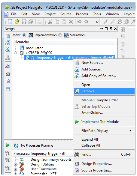
Illustration 2.11: Remove option
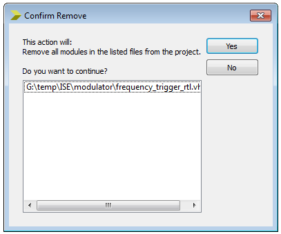
Illustration 2.12: Confirm Remove dialog box
2.3.1 Creating a Module Using an Text Editor
Here are the steps for creating a module using an text editor:
- Open an text editor (for better usability, take one with VHDL code support)
- Insert the VHDL code and add the frequency_trigger_rtl module header
- Save the file as module_name (e.g. frequency_trigger_rtl) into your working directory
- Change the ending from *.txt to *.vhd
- Optional: Launch Project Navigator (if it is not already launched)
- Optional: Open “Modulator" project (modulator.xise) (if it is not already opened)
- In the Project Navigator, select Project / Add Source... option, see Illustration 2.13
- In the Add Source dialog box, browse to the project working directory and select the frequency_trigger_rtl.vhd source file and click Open
- In the Adding Source Files... dialog box, select All in the Association drop-down menu and click OK, see Illustration 2.14
- After adding frequency_trigger_rtl.vhd source file into modulator project, it should appear in the Hierarchy window, under the modulator project, see Illustration 2.15.
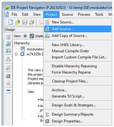
Illustration 2.13: Add Source option
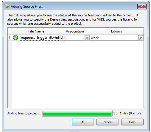
Illustration 2.14: Adding Source Files dialog box

Illustration 2.15: frequency_trigger_rtl.vhd source file in the Hierarchy window
Note: Double-click on the frequency_trigger – rtl (frequency_trigger_rtl.vhd) source file in the Hierarchy window and your source file should appear in the text editor on the right side of the ISE Project Navigator.
Frequency Trigger VHDL model:
library ieee;
use ieee.std_logic_1164.all;
use ieee.std_logic_arith.all;
use ieee.std_logic_unsigned.all;
entity frequency_trigger is
generic(
div_factor_freqhigh_g : integer := 0; -- input clock division factor when sw0 = '1'
div_factor_freqlow_g : integer := 0 -- input clock division factor when sw0 = '0'
);
port(
clk_in : in std_logic; -- input clock signal
sw0 : in std_logic; -- signal used for selecting frequency
freq_trig : out std_logic -- output signal which frequency depends on the sw0 state
);
end;
architecture rtl of frequency_trigger is
signal freq_cnt_s : integer := 0; -- clock counter
signal sw0_jmp : std_logic := '0'; -- variable who is tracking sw0'event
begin
freq_ce_p : process -- create and select frequency
begin
wait until rising_edge(clk_in);
freq_cnt_s <= freq_cnt_s + 1; -- increment
freq_trig <= '0';
case sw0 is -- select sine frequency
when '0' => -- frequency for sw0 = '0'
if (sw0_jmp = '1') then
freq_cnt_s <= 0; -- reset
sw0_jmp <= '0';
end if;
if (freq_cnt_s = div_factor_freqlow_g - 1) then
freq_trig <= '1';
freq_cnt_s <= 0; -- reset
end if;
when '1' => -- frequency for sw0 = '1'
if (sw0_jmp = '0') then
freq_cnt_s <= 0; -- reset
sw0_jmp <= '1';
end if;
if (freq_cnt_s = div_factor_freqhigh_g - 1 ) then
freq_trig <= '1';
freq_cnt_s <= 0; -- reset
end if;
when others => null;
end case;
end process;
end;
-
In the Hierarchy window, select the desirable module_name (frequency_trigger – rtl), in the Processes window expand Synthesize - XST and double-click on the Check Syntax option, see Illustration 2.16
Note: Please bear in mind that the Implementation option in the Design View must be selected.
- Correct any errors before proceeding
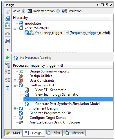
Illustration 2.16: Check Syntax option
Note: Information about creating the Frequency Trigger Module, you can also find in the Lab 3: “Creating Frequency Trigger Module”.
2.4 Creating Test Bench
- Usage: used to verify correct operation of the frequency_trigger module defined in the frequency_trigger_rtl.vhd file
- Test bench internal signals:
- clk_in_s: input clock signal
- sw0_s: input signal used to select output signal frequency
- freq_trig_s: output signal which frequency depends of the sw0_s signal state
- Generics:
- div_factor_freqhigh_g: input clock division factor when sw0 = '1'
- div_factor_freqlow_g: input clock division factor when sw0 = '0'
- File name: frequency_trigger_tb.vhd
We are creating a test bench to verify the correctness of a design or model.
Here are the steps necessary for creating an test bench:
- In the ISE Project Navigator, select Project / New Source... option from the main menu or click on the New Source button in the Design window
- In the Select Source Type dialog box, select VHDL Test Bench and enter testbench_name (frequency_trigger_tb) in the File name field, see Illustration 2.17
- Click Next to select a source with which to associate the new source
- In the Associate Source dialog box, select the frequency_trigger module and click Next, see Illustration 2.18
- In the Summary window, click Finish to finish with the test bench creation, see Illustration 2.19
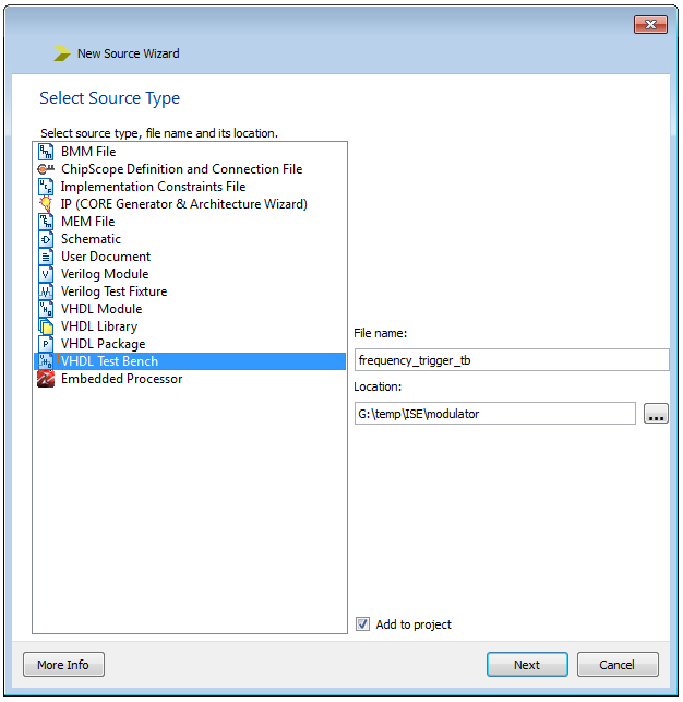
Illustration 2.17: Select Source Type dialog box – VHDL Test Bench
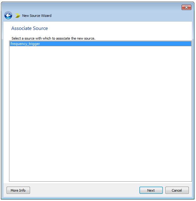
Illustration 2.18: Associate Source dialog box
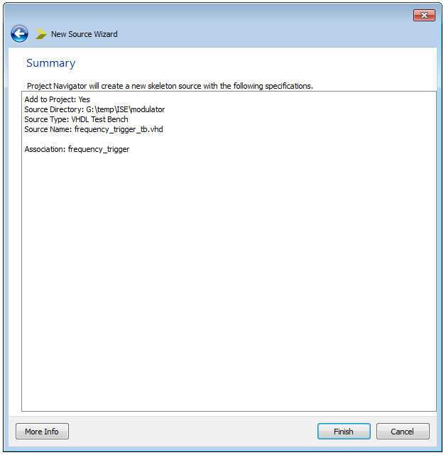
Illustration 2.19: Summary dialog box for the test bench file
- After adding frequency_trigger_tb.vhd source file into modulator project, it should appear in the Hierarchy window, under the modulator project. Please bear in mind that the Simulation option in the Design View must be selected, see Illustration 2.20.
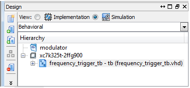
Illustration 2.20: frequency_trigger_tb.vhd file in the Hierarchy window
- Double-click on the created frequency_trigger_tb.vhd source file to see what the tool has created for us
The ISE software now have created a standard structure for a test bench, which contains:
- Test bench description
- Component declaration: Based on the Unit Under Test (UUT) that we have designated
- Signal declarations: Using the same names as the ports in the UUT module
- Time constants for clock generation
- Instantiation and port map: Connected the declared component and signals
- Stimulus process: Created wait statements for stimulus generation
Important: The automatically generated code is not very handsome and clear, and the recommendation is to modify it. Here are the steps for modifying:
- set all text to lower case
- remove all time constants, clock process definitions, stimulus processes, port map definitions and comments
- rename architecture description into a architecture_tb(frequency_trigger_tb)
- suffix all signals with a “_s” (for example: clk_in_s) and update it in the port map on the right side
- create a module - and a revision-description as comment (header)
- set all in/outputs and signals in alphabetical order and comment them
Note: As you can see there are a lot of things for modifying. For better designs, our recommendation is not to use the GUI module inserter. Instead of that, create a test bench file in an text editor, rename it to module_name_tb.vhd and insert it into your project.
All the steps for creating a module using an text editor are explained in the previous Sub-chapter 2.3.1 Creating a Module Using an Text Editor.
Before you create a new test bench file using an text editor, don't forget to remove frequency_trigger_tb.vhd source file from the project.
- Create a test bench file using the code below:
Frequency Trigger test bench:
library ieee;
use ieee.std_logic_arith.all;
use ieee.std_logic_unsigned.all;
use work.modulator_pkg.all;
entity frequency_trigger_tb is
generic(
div_factor_freqhigh_g : integer := 2; -- input clock division factor when sw0 = '1' (an example)
div_factor_freqlow_g : integer := 4 -- input clock division factor when sw0 = '0' (an example)
);
end;
architecture tb of frequency_trigger_tb is
signal clk_in_s : std_logic := '1'; -- input clock signal
signal freq_trig_s : std_logic := '1'; -- signal which frequency depends on the sw0 state
signal sw0_s : std_logic := '0'; -- signal for selecting frequency
begin
freq_ce : entity work.frequency_trigger (rtl) -- frequency trigger instance
generic map(
div_factor_freqhigh_g => div_factor_freqhigh_g,
div_factor_freqlow_g => div_factor_freqlow_g
)
port map(
clk_in => clk_in_s,
sw0 => sw0_s,
freq_trig => freq_trig_s
);
clk_in_s <= not (clk_in_s) after per_c/2; -- generates 50 MHz input clock signal;
sw0_s <= '1' after 200 ns;
end;
Note: As you can see from the code above, you must include modulator_pkg.vhd source file into your modulator project. In the modulator_pkg.vhd file is defined per_c constant that will be used in this test bench. This package will be explained in detailed later, in Chapter 4. SINE PACKAGE, where you can also find the whole modulator_pkg.vhd source code.
To include modulator_pkg.vhd source file into your modulator project, use Project / Add Source... option from the ISE Project Navigator.
2.5 Simulating (with ISim)
Simulation is a process of emulating the real design behavior in a software environment. Simulation helps verify the functionality of a design by injecting stimulus and observing the design outputs. Simulators interpret HDL code into circuit functionality and display logical results.
The ISE tool is integrated with the Xilinx ISim logic simulation environment. The ISE tool enables you to add and mange simulation test benches in the project. You can launch behavioral simulation prior to synthesis using RTL sources and launch timing simulation using post-implementation simulation model, that will be generated by the ISE tool after completing the design implementation process.
After you have entered the code for the input stimulus in order to perform simulation, follow the next steps:
- In the Hierarchy window, right-click and then select Design Properties... option, see Illustration 2.21
- In the Design Properties dialog box, verify that ISim (VHDL/Verilog) option is selected in the Simulator field, and VHDL is selected in the Preferred Language field, see Illustration 2.22
- Click OK
- Select Simulation option in the Design View (above the Hierarchy window) to switch Implementation with the Simulation view
- If necessary, select Behavioral Simulation from the drop-down list
- Select testbench_name (frequency_trigger_tb.vhd) in the Hierarchy window
- In the Processes window, expand ISim Simulator and double-click on the Behavioral Check Syntax (only available for ISE Simulation), see Illustration 2.23
- Correct any errors before proceeding
- In the Processes window, double-click on the Simulate Behavioral Model, see Illustration 2.23
- Assuming no errors, your simulation result should look similar to the Illustration 2.24
- Optional: If you want to insert further internal signals from your simulated file, click on the file in the Instance and Process Name window and drag-and-drop the signal from the Object Name window into the waveform window. Now you have to restart and rerun your simulation.
- Optional: If you want to restart and rerun simulation for specific time, see Illustration 2.25
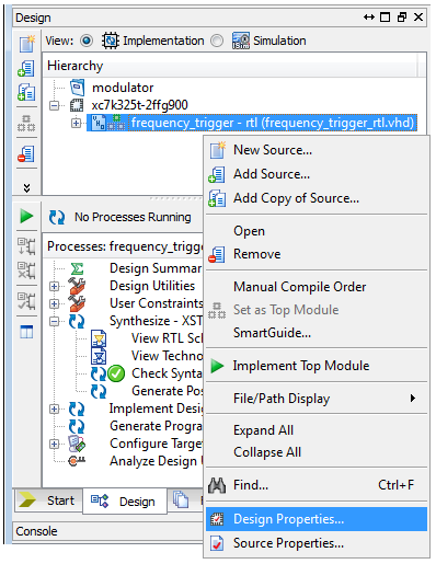
Illustration 2.21: Design Properties option
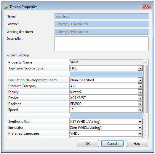
Illustration 2.22: Design Properties dialog box
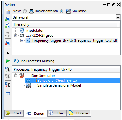
Illustration 2.23: Behavioral Check Syntax command
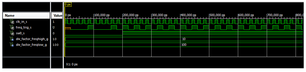
Illustration 2.24: Simulation Results

Illustration 2.25: ISim Simulator Simulation Controls
ISim Simulator Simulation Controls has the following buttons that the user can use to control the simulation process:
- Restart - restarts the simulation from “time 0”
- Run All - run the simulation until there are no more events
- Run for the time specified on the toolbar – runs the simulation for the specified amount of time
- Step – runs the simulation until the next breakable line
- Break – stops the running simulation at the next breakable line
- Re-launch – re-launch current ISE simulator
Note: Information about creating a Frequency Trigger test bench and simulating a design using ISim simulator, you can also find in the Lab 4:”Frequency Trigger Verification”.