7. PWM
7.1 Description
-
Usage: This module will generate an PWM signal modulated using the digital sine wave from the Digital Sine module. This module will be composed of two independent modules. One will be the Frequency Trigger, for generating two different frequencies and the second one will be the Finite State Machine (FSM), for generating the PWM signal.
Frequency Trigger module is the same module explained as in the Chapter 2. FREQUENCY TRIGGER.
FSM module will generate the PWM signal. It will generate the PWM signal with correct duty cycle for each period based on the current amplitude value of digital sine signal, that is stored in the ROM. State diagram of the FSM is shown on the Drawing 7.2.
- Block diagram:
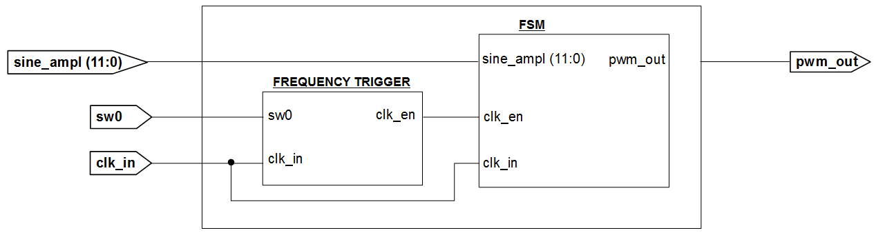
Drawing 7.1: PWM block diagram
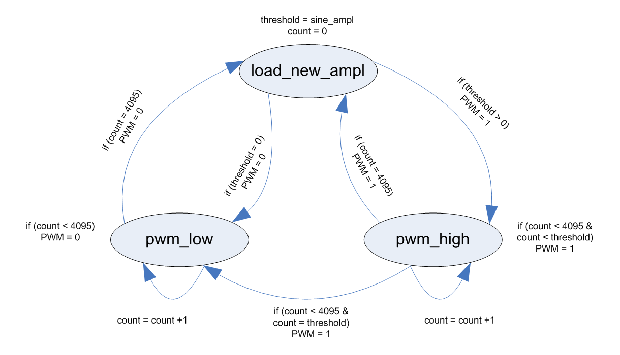
Drawing 7.2: FSM state diagram
- Input ports:
- clk_in: input clock signal
- sw0: input signal from the on-board switch, used for changing output signal frequency
- sine_ampl: current amplitude value of the sine signal
- Output ports:
- pwm_out: pulse width modulated signal
- Generics:
- width_g: the number of bits used to represent amplitude value
- div_factor_freqhigh_g: input clock division when sw0 = '1'
- div_factor_freqlow_g: input clock division when sw0 = '0'
- File name: pwm_rtl.vhd
7.2 Creating Module
To create PWM module, use steps for creating modules, Sub-chapter 2.3.1 Creating a Module Using an Text Editor.
PWM VHDL model:
library ieee;
use ieee.std_logic_1164.all;
use ieee.std_logic_arith.all;
use ieee.std_logic_unsigned.all;
entity pwm is
generic(
width_g : integer range 1 to 99 := 12; -- the number of bits used to represent amplitude value
div_factor_freqhigh_g : integer := 0; -- input clock division when sw0 = '1'
div_factor_freqlow_g : integer := 0 -- input clock division when sw0 = '0'
);
port(
clk_in : in std_logic; -- input clock signal
sw0 : in std_logic; -- signal made for selecting frequency
sine_ampl : in std_logic_vector(width_g-1 downto 0); -- current amplitude value of the sine signal
pwm_out : out std_logic -- pulse width modulated signal
);
end;
architecture rtl of pwm is
type state_type is (load_new_ampl, pwm_high, pwm_low); -- states s0, s1, s2
signal state: state_type ;
signal ce_s : std_logic := '0'; -- clock enable signal for the fsm
begin
process1: process (clk_in)
variable treshold : integer range 0 to ((2**width_g)-1) := 0; – integer range 0 to 4095 (in our case)
variable count : integer range 0 to ((2**width_g)-1) := 0; – integer range 0 to 4095 (in our case)
begin
if (clk_in = '1' and clk_in'event) then
if (ce_s = '1') then
case state is
when load_new_ampl =>
treshold := conv_integer (sine_ampl);
count := 0;
if (sine_ampl > 0) then
state <= pwm_high;
elsif (sine_ampl = 0) then
state <= pwm_low;
end if;
when pwm_high =>
count := count + 1;
if (count < ((2**width_g)-1) and count < treshold) then
state <= pwm_high;
elsif (count = ((2**width_g)-1)) then
state <= load_new_ampl;
elsif (count < ((2**width_g)-1) and count = treshold) then
state <= pwm_low;
end if;
when pwm_low =>
count := count + 1;
if (count < ((2**width_g)-1)) then
state <= pwm_low;
elsif (count = ((2**width_g)-1)) then
state <= load_new_ampl;
end if;
end case;
end if;
end if;
end process process1;
process2 : process (state)
begin
case state is
when load_new_ampl => pwm_out <= '0';
when pwm_high => pwm_out <= '1';
when pwm_low => pwm_out <= '0';
end case;
end process process2;
fsm_ce: entity work.frequency_trigger(rtl) -- instance of the frequency trigger
generic map (
div_factor_freqhigh_g => div_factor_freqhigh_g,
div_factor_freqlow_g => div_factor_freqlow_g
)
port map (
clk_in => clk_in,
sw0 => sw0,
freq_trig => ce_s
);
end;
7.3 Creating Test Bench
- Usage: used to verify correct operation of the PWM module defined in the pwm_rtl.vhd file
- Test bench internal signals:
- clk_in_s: input clock signal
- sw0_s: input signal from the on-board switch, used for changing output signal frequency
- sine_out_s: current amplitude value of the sine signal
- pwm_s: pwm signal
- Generics:
- cntampl_value_g: threshold value for counter, it's value should be equal to (2^depth)-1
- depth_g: the number of samples in one period of the signal
- width_g: the number of bits used to represent amplitude value
- File name: pwm_tb.vhd
We will now create a test bench for PWM module (pwm_tb.vhd). We will use the same steps as for creating frequency_trigger_rtl.vhd module, explained in Sub-chapter 2.3.1 Creating a Module Using an Text Editor.
library ieee;
use ieee.std_logic_1164.all;
use ieee.std_logic_arith.all;
use ieee.std_logic_unsigned.all;
use work.modulator_pkg.all;
entity pwm_tb is
generic(
cntampl_value_g : integer := 255; -- threshold value for counter, it's value should be equal to (2^depth)-1
depth_g : integer range 1 to 99 := 8; -- the number of samples in one period of the signal
width_g : integer range 1 to 99 := 12 -- the number of bits used to represent amplitude value
);
end;
architecture tb of pwm_tb is
signal clk_in_s : std_logic := '0'; -- input clock signal
signal sine_out_s : std_logic_vector(width_g-1 downto 0) := (others=>'0'); -- current amplitude value of the sine signal
signal sw0_s : std_logic := '0'; -- signal made for selecting frequency
signal pwm_s : std_logic := '0'; – pwm signal
begin
dut1 : entity work.sine_top -- sine_top instance
generic map(
cntampl_value_g => cntampl_value_g,
depth_g => depth_g,
width_g => width_g,
div_factor_freqhigh_g => 10*(2**width_g), -- 10*4096=40960
div_factor_freqlow_g => 20*(2**width_g) -- 20*4096=81920
)
port map(
clk_in => clk_in_s,
sine_out => sine_out_s,
sw0 => sw0_s
);
dut2 : entity work.pwm – pwm instance
generic map(
width_g => width_g,
div_factor_freqhigh_g => 10,
div_factor_freqlow_g => 20
)
port map(
clk_in => clk_in_s,
sw0 => sw0_s,
sine_ampl => sine_out_s,
pwm_out => pwm_s
);
clk_in_s <= not (clk_in_s) after per_c/2; -- 50 MHz input clock signal
sw0_s <= '0', '1' after 1 ms;
end;
7.4 Simulating
After you have entered the code for the input stimulus in order to perform simulation:
- You can start your simulation (see Chapter 3.4 Simulating)
- Simulate your design for 100 ms (see Chapter 2.5 Simulating (with ISim) – step 12.)
- Assuming no errors, your simulation result should look similar to Illustration 7.1.
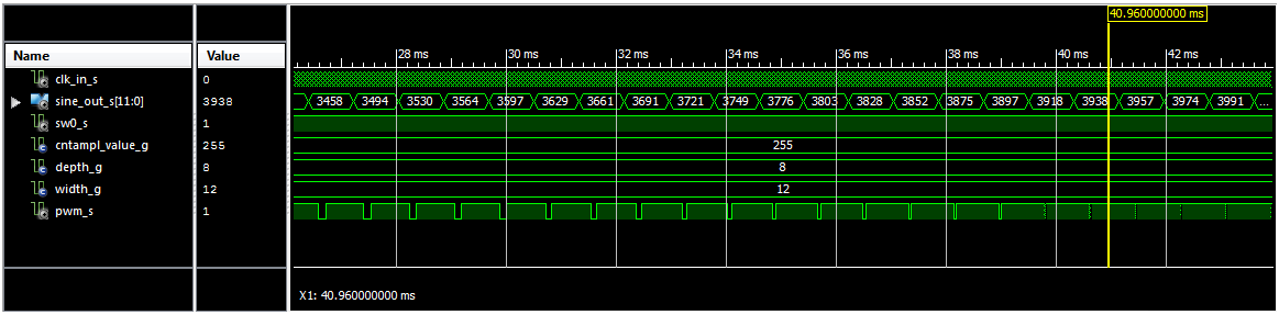
Illustration 7.1: Simulation Results
Note: All the information about creating the PWM Module, its FSM state diagram, generating the PWM test bench and simulating the PWM design, you can also find in the Lab 9: “Creating PWM Module”.